Definition of an H. S. R. Algorithm.
Copyright (c) Susan Laflin. August 1999.
One of the earliest attempts to produce a rigorous definition of these algorithms occurs in the text by Giloi. Since it is still relevant, let us consider it: An hidden-surface algorithm is said to consist of five components, namely:
O 	The set of objects in 3D space (input data).
S  	The set of objects in 2D space (results).
I  	The set of intermediate representations (workspace). Some
	algorithms require little or no intermediate storage. These
	representations, if used, may be in either 2D or 3D.
T  	The set of transition functions, usually implemented as
	subroutines or procedures. The following five transition
	functions will be required in some form.
		PM = Projective Mapping.
		IS = Inter-Section Function.
		CT = Containment Test.
		DT = Depth Test.
		VT = Visibility Test.
M 	Strategy Function or Overall Method. This specifies the
	order in which the transition functions are applied to
	the input data to produce the results and it may also
	include instructions to display the results.
In fact this may be an over simplification, since we frequently find that the transition functions are used in combination with each other. For example, to decide whether one point in 3D space is hidden by another, it will usually be necessary to apply a combination of both Projective Mapping and Depth Test. Projective Mapping may be either Perspective or Orthogonal. Consider the situation where we have a view point V on one side of the objects to be drawn and are projecting them on to a plane on the far side of the objects. Now assume we have rotated the entire figure so that the plane is z=0, the viewpoint is on the z-axis (coordinates 0,0,Z), and all other z values lie between 0 and Z.
Now let us consider two overlapping graphical elements, to determine which of the two is closer to the viewpoint and hence which covers the other when the diagram is drawn. In the following discussion, it is assumed that the graphical elements are plane polygonal facets and each vertex of one facet is tested against all vertices of the other.
a) Perspective projection.
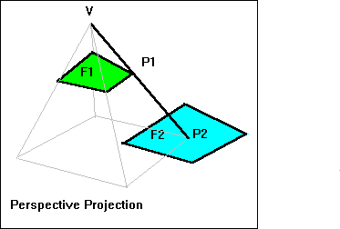
Consider any two points P1 and P2. P2 is hidden by P1 if and only if
(i) V, P1 and P2 are co-linear.
(ii) P1 is closer to V. i.e. VP1 < VP2.
Consider the test-point P1 (usually a vertex of the first facet F1) and facet F2. Connect the viewpoint V and test-point P1 and calculate P2, the intersection of the line VP1 (continued if necessary) and the facet F2. Calculate the lengths of VP1 and VP2.

Then if VP2 is greater than VP1, P1 is not hidden by F2.
If VP2 is less than VP1 then P1 is hidden by F2.
If VP1 = VP2, then the two points coincide and we may choose which of them
to consider visible.
b) Orthogonal Projection.
Again the viewer is at the height V and looking down on the plane z=0, but
now all the lines are parallel. Indeed for an orthogonal projection, they
are all perpendicular to the plane z=0 and so parallel to the z-axis. So the
point P2 is hidden by P1 if and only if
(i) The x and y coordinates of P1 and P2 are equal.
(ii) The z-coordinate P1(z) > P2(z).
This is equivalent to moving the point V a very large distance from the plane z=0 ("V tends to infinity").
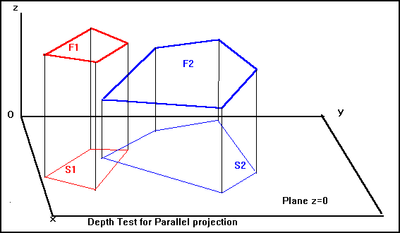
Consider the projection onto the plane z=0 and use the values of z to assign priorities to the faces. In this case, we wish to compare facets F1 and F2. After projection onto the plane z=0, F1 is projected on to S1 and F2 is projected onto S2. The intersection of S1 and S2 is called S. If S is empty, then the projections do not overlap and the priority is irrelevant.

Any point (x,y,0), lying in S, corresponds to the point (x,y,z1) in F1 and the point (x,y,z2) in F2. If z1 is greater than z2 for all these points, then "F1 has priority over F2". However if this is true for some points in S and false for others, then the two facets intersect each other and we cannot assign priorities. It will be necessary to calculate the line of intersection of the two facets and split one of them along this line. If F1 is split into F1a and F1b, then we can number them so that F1a has priority over F2 and F2 has priority over F1b.
Using these priorities, it is possible to get a unique ordering, showing which facets lie in front of which others and use this to provide the correct output to draw the visible facets.
Intersection Function
Note that in each of these cases, it was necessary to discuss the intersection of the projection of a vertex of one facet and the projection of the other facet. This may be dealt with by use of the Intersection Function, which defines how to calculate the intersection of two graphic elements. Other examples are the intersection of two lines, the intersection of two segments (lines of fixed length) or the intersection of a line and a plane. In this actual case, it is probably more relevant to use a Containment Test.
Containment Test
The Containment Test considers the question "Does the point P lie inside the polygon F ?" and returns the result "true" or "false". It is usually applied after projection into two dimensions and so the methods discussed in that section are immediately applicable. Either the angle test or the intersection test may be used.
Visibility Tests
So far, we have discussed the special case of one or more objects defined as plane facets and considered whether or not one of the facets obscures another. This is a very slow process, especially when all of the very large number of facets have to compared with all the others. There is one very simple consideration which will about halve the number of facets to be considered. If we assume that the facets form the outer surfaces of one or more solid objects, then those facets on the back of the object (relative to the viewing position) cannot be seen and so a test to identify these will remove them from the testing early in the process.
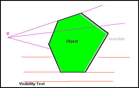
This uses a "Visibility Test" which is applied to solid objects, to distinguish between the potentially visible "front faces" and the invisible "back faces". If our picture consists of a single convex object, then all the potentially visible faces are visible and the object may be drawn very quickly and easily.
If a perspective projection is being used, then the "line of sight" is the line from the viewpoint V to the point on the surface. However, if a parallel projection is being used, then the relevant line is one parallel to the viewing direction which passes through the point on the surface. In either case, let this direction be denoted by the vector d.
The surface normal, denoted by n, is the outward-pointing normal from this point, normal to the surface of the plane. To decide whether the plane is potentially visible or always invisible, it is necessary to consider the angle between d and n and we may use the dot product d.n to decide this. Let A be the angle between these vectors. If A is greater than 90degrees, then the surface is potentially visible, otherwise the surface is invisible. If both vectors are scaled to have unit length, so that we are dealing with direction cosines, then the dot product gives the value of cosA. Thus the face is potentially visible if the dot product is negative.

In the above figure, the parallel projection has d = [1,0,0] and face A has outward normal n1 = [-1,2,0] while face B has outward normal n2 = [1,0,0]. The dot product of the visible face A has value -1 and the dot product of the invisible face has the value 1. When the dot product is zero the face is "edge-on" to the viewing direction and may be omitted.
Strategy Function or Overall Method.
In discussing the method used by any Hidden-surface Removal Algorithm, we shall also need to discuss the input data (O) and the results (S) and indeed it may be useful to classify these algorithms according to the form of input data they can handle. The set (I) of intermediate representations may be important in deciding practical aspects such as the total amount of storage needed by the algorithm, and will be closely connected with the precise form of some of the Transition functions used. Let us consider a number of algorithms, classified according to the form of their input data. Because the same general method may have considerable variation in the details, we shall tend to get groups of algorithms which differ only in their fine detail.